Modern vehicles rely heavily on software-controlled braking systems to maintain safety during emergency stops. One of the most important of these is the Anti-Lock Braking System (ABS).
ABS prevents wheels from locking during hard braking, allowing the driver to:
✔ maintain steering control
✔ reduce stopping distance on most surfaces
✔ avoid skidding
✔ remain stable on split-µ roads
In this article we’ll cover:
• What ABS really does
• Tire–road physics
• Slip ratio
• ABS control logic
• Sensors & actuators
• Typical ECU architecture
• Simulation models
• How engineers test ABS
🚗 Why Wheels Lock — The Physics
When braking, the brake caliper applies torque to the wheel:
Brake torque → wheel deceleration → tire force → vehicle deceleration
If braking torque exceeds what the road can transmit, the tire slides instead of rolling.
Sliding tires generate:
• less longitudinal force
• no lateral force → no steering
• instability
So the goal is not maximum brake pressure — it is maximum tire–road friction.
📉 Slip Ratio — The Key ABS Variable
ABS is based on a quantity called longitudinal slip:λ=VV−Rω
Where:
• V = vehicle speed
• R = tire radius
• ω = wheel angular speed
Interpretation:
| Slip | Meaning |
|---|---|
| 0 | Free rolling |
| 0.1–0.2 | Peak braking force |
| >0.3 | Near wheel lock |
| 1.0 | Fully locked |
ABS tries to hold slip near the peak region, typically around:
0.12 – 0.18
🛣️ Tire–Road Friction Curve
Every road surface has a µ–slip curve:
µ
|           dry asphalt
|         /\
|        /  \
|       /    \      wet
|      /      \   /
|_____/________\_/________ slip
        ice
Peak friction differs:
| Surface | µ peak |
|---|---|
| Dry asphalt | ~1.0 |
| Wet | ~0.6 |
| Ice | ~0.2 |
ABS does not know the road type directly — it infers it from wheel behavior.
🧠 What ABS ECU Actually Does
An ABS controller runs in real time inside the brake ECU.
Each wheel is controlled independently.
Inputs:
• wheel speed sensors
• estimated vehicle speed
• brake pedal request
• hydraulic pressure sensors (optional)
Outputs:
• valve commands
• pump motor control
• pressure modulation
The ECU executes at:
100–500 Hz typical
🔁 Classical ABS Control Strategy
Most production ABS systems use a state-machine approach:
Three main states:
BUILD
→ increase pressure
HOLD
→ keep pressure constant
RELEASE
→ dump pressure
Transitions depend on:
• slip thresholds
• wheel deceleration
• wheel recovery
• vehicle speed
Example logic:
if slip > 0.22 → RELEASE
if slip < 0.08 → BUILD
otherwise → HOLD
This produces the familiar ABS pulsing during emergency braking.
⚙️ Hydraulic Actuation
ABS does not directly move brake pads.
Instead it commands:
• inlet valves
• outlet valves
• accumulator
• return pump
This allows rapid modulation of brake pressure:
Pedal → master cylinder → ABS modulator → caliper
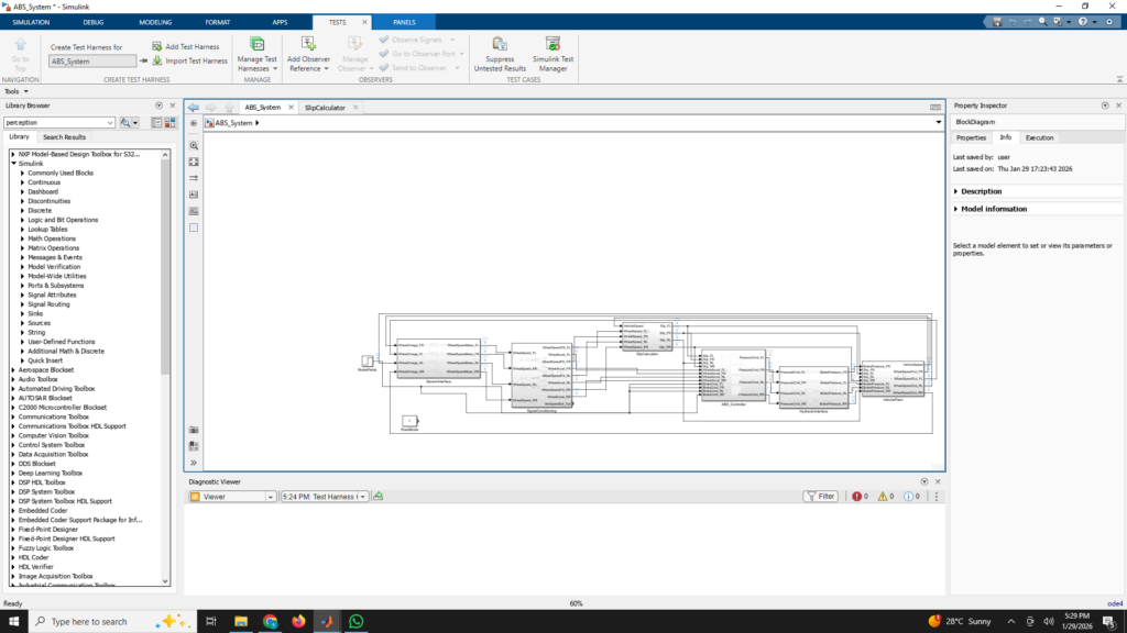
🧩 Typical Software Architecture
In a model-based development environment (Simulink, AUTOSAR, etc.), ABS is structured as:
VehiclePlant
   ↓
Wheel Speed Sensors
   ↓
Signal Conditioning / Filtering
   ↓
Slip Calculator
   ↓
ABS Controller
   ↓
Hydraulic Model
   ↓
Vehicle Dynamics
Each block can be:
• unit tested
• MIL tested
• SIL verified
• HIL validated
🧪 How Engineers Test ABS
ABS software is validated in multiple stages:
🔹 Model-in-the-Loop (MIL)
Simulink plant + controller.
🔹 Software-in-the-Loop (SIL)
Generated C code vs model.
🔹 Hardware-in-the-Loop (HIL)
Real ECU connected to real-time vehicle simulator.
🔹 Proving Ground
Ice tracks, split-µ roads, wet asphalt.